DLE combustion mapping for LM series gas turbines
Aero Controls Services

Dry Low Emissions (DLE) Mapping

Specialist DLE combustion mapping for LM2500 and LM6000 series gas turbines.

DLE combustor fuel nozzles — LM series premix nozzle array
DLE mapping in progress — HMI and real-time data monitoring

Dry Low Emissions (DLE) Combustion Mapping

Aero Controls has been providing specialist DLE combustion mapping services for over 21 years, with unparalleled experience across all LM DLE engine variants and fuel types — making us one of the leading independent DLE mapping specialists worldwide.

Our DLE mapping services optimise combustion performance to achieve the lowest possible emissions while maintaining engine reliability, fuel efficiency and operational flexibility. We use our own Testo emissions measurement equipment and carry out a full suite of mapping, schedule optimisation and compliance testing on site.

All mapping results are compiled into a detailed report including mapping data tables, emissions statistics, combustion schedule plots, mode overlap boundaries and fuel flex analysis — delivered to the client on completion.

DLE Combustion Technology

Technical background on the DLE combustor hardware, combustion theory, control system architecture and mapping tools used during our field mapping operations.

Combustor Hardware

LM6000 Combustor — AFT looking forward: Inner (green) and Outer (orange) cup positions, with Ignition (blue) at position 6. Shows 11 combustor positions with inner/outer premix rings.
DLE Combustor LM6000PD — DLE Fuel System: A Ring (FMV A, 30 cups, 15 ELBO gas), B Ring (FMV B, 30 cups), C Ring (FMV C, 15 cups, no ELBO gas), with ELBO valve at position 6.

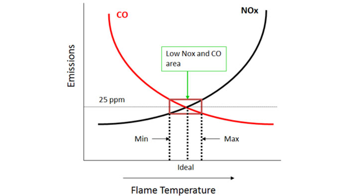
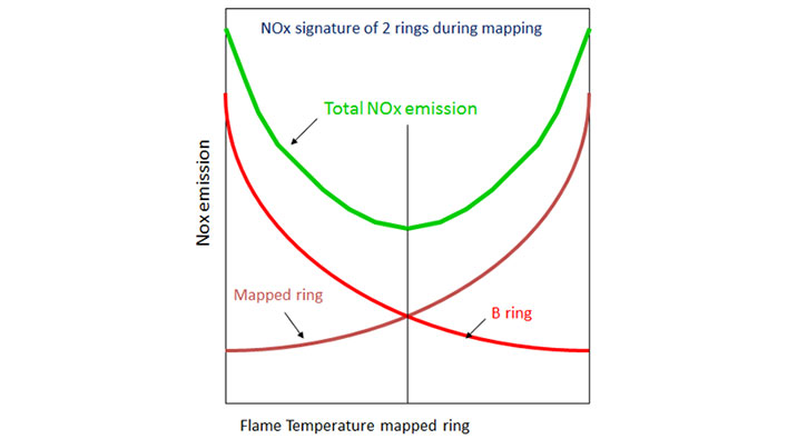
Combustion Theory & Mapping Principles

What — How — Why — When: combustor mapping measures operational boundaries (acoustic zones, blowout regions) and translates data into control schedules — ring flame temperature adjustment, optimal combustion/emissions and window determination.
NOx & CO vs Flame Temperature: the low NOx and CO operating window (Min–Max ideal range) below 25 ppm. Flame temperature must be precisely controlled to keep both NOx and CO within specification simultaneously.
NOx signature of two rings during mapping: as the mapped ring flame temperature is adjusted, total NOx forms a minimum at the optimal crossover point between mapped ring and B ring NOx curves.
HP turbine inlet temp (T4) vs power — combustion staging steps: B → BC/2 → BC → AB → ABC. Each staging step has defined transition points where the engine moves between combustion modes as power increases.
Mode overlap zones: staging transition windows showing Min/Max operating boundaries and the control path through mode transitions — ensuring smooth, stable staging between combustion modes.

Control System Architecture
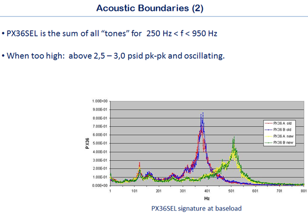
FMV valve control architecture: P1/P2 pressure taps → actuator (3103 valve) ↔ resolver ↔ EM module. Press input card and software (SN.vlv, WF demand, mapping tables, natural-gas parameters); 2-channel position card / RTSIO receives valve position demand.
GAP application structure: GAP application #1 — core fuel control communicates through interface blocks to GAP application #2 — hardware definition / custom sequencing. DLE fuel control logic is distributed across inter-connected GAP applications.
DLE combustor TFLAME/airflow staging — LM6000PD: S_STGVLV block → inner pattern ID → inner ring valves; outer pattern ID → outer ring valves, driving the inner and outer ring staging valve demands.
DLE combustor — LM6000PF / core S2 — liteoff: T48SEL/T3SEL subtract → compare blocks, AND/OR logic gates → trigger latch → liteoff output used for flame ignition detection and control sequencing.
LM6000PD DLE combustor mapping parameters screen: TFLAME schedule adjustment showing BULK, MAX, MIN, INNER and OUTER with engine pressure, temperatures, speeds, combustor parameters and airflow parameters.

Acoustic Boundaries

Acoustic boundaries: PX36SEL is the sum of all tones for 250 Hz < f < 950 Hz. When too high (above 2.5–3.0 psid pk-pk) the engine is oscillating. PX36SEL frequency spectrum at baseload showing old vs new sensor comparison.

Sample Mapping Outputs

Illustrative examples of the data, charts and analysis contained in a typical DLE mapping report delivered to the client.

Sample mapping data — BRN DMD, MW, T2, BLEED, TFLAME, NGG, NPT, PS3, T3, T48, PX36, TFLMIN/MAX, raw NOx/CO, O2 and corrected NOx.
Gas turbine statistics comparison — MW vs corrected NOx ppm and emission rate across N2 10.5%, 6% and 3% fuel nitrogen. Spec limit
Gas turbine statistics comparison — MW vs corrected NOx ppm and emission rate across N2 10.5%, 6% and 3% fuel nitrogen. Spec limit <25 ppm corrected NOx and <3.6 m/s.
Fuel flex bias analysis — AB9C & ABC mode, min and max lines plotted against Modified Wobbe Index (MWI) for engines 1411 through 1621.
AB9C and ABC mode inner & outer schedules — TFLAME (°F) plotted vs T3 (°F) for all engines across combustion modes.
Burner mode overlap analysis — BC to AB, AB to AB9C and AB9C to ABC mode overlap boundaries (max & min) for engines 1521, 1611 and 1621.
Mapping schedule chart — inner (INR) and outer (OTR) TFLAME schedules plotted against T3 showing new max/avg/min vs spec max/min boundaries.

Our Emissions Measurement Equipment

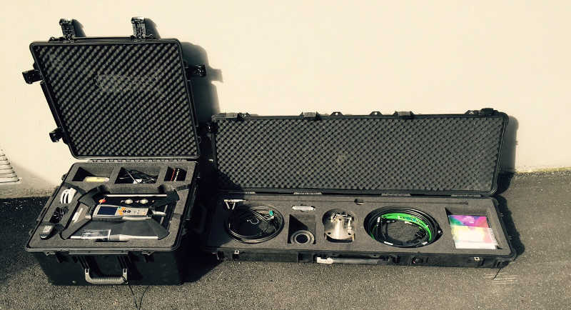
Aero Controls operates its own Testo emissions measurement equipment for deployment worldwide. All equipment is maintained in calibration and transported in custom Pelican cases.

Testo Emissions Analyser

Testo Emissions Analyser

Testo portable emissions analyser in custom Pelican transport case. Measures NOx, CO, O2, CO2 and UHC simultaneously for real-time emissions quantification during mapping.

Emissions Probe & Accessories

Emissions Probe & Accessories

Testo emissions probe kit with sampling tubes, interconnect cables, flange adaptor and consumables in a custom foam-cut Pelican long-case for field transport.

Complete Analyser & Probe Setup

Complete Analyser & Probe Setup

Full Testo emissions measurement system — analyser unit alongside probe case for simultaneous on-site deployment at gas turbine packages.

Transport Cases

Transport Cases

Rugged Pelican transport cases (long-case for probe, standard case for analyser), purpose-built for safe air/road freight and site deployment worldwide.

Enquire About DLE Mapping

Contact our team to discuss DLE combustion mapping for your gas turbine package. We work globally and can mobilise our equipment and engineers to your site.

All services